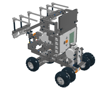
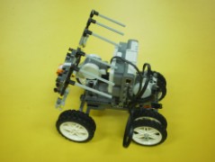
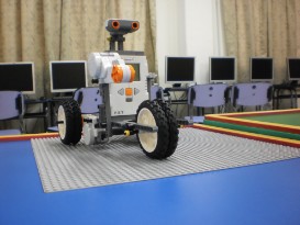
Our final robot design: Moon Rover 13.0
The Moon Rover 13.0 comprises of one motor at the back of the robot, one motor in front to the robot and a third motor to grab the Helium 3.
We originally had an Ultrasonic Sensor at the top of the robot (as shown in the below left picture) but, we removed of it in the eleventh hour because it did not function properly in the last minute. As we mentioned earlier, the front wheels still have gears to maintain its turning position.
The Moon Rover 13.0 is able to hold Helium 3, rest at the POEL, capture the mission video, exit the Lander Dismount and take a picture of the Heritage Artifacts as it has a special cage to keep the camera while it takes the mission video.
Even though we were not able to complete all the tasks in the MoonBots game challenge, we have so much fun in designing and programming the robot. At the same time, we have to finish up our school homework and sit for our coming examination in early September.
Please view our robot design in 3D at the following link below.
https://picasaweb.google.com/113490659192628215135/TechnoInventorsRobotDesignIn3D#
-Kenneth
 Robot Design without Ultrasonic sensor
| 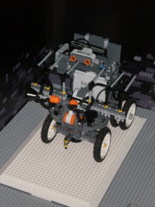 Robot Design with Ultrasonic sensor
|
Our fourth robot design on 31 July 2011
Even though the robot design is what we desired for, we always have issue with the front wheels. Although the front wheels can help the robot to turn left or right easily, but it always deviates to the left or right from the Landing Base to the playing field. We found out that meshed gears can help the wheels to turn faster or slower.
So, we use the gearing down system to control the wheels in turning left or right on the playing field. Instead of using two tyres at each side, now we just use one tyre for each side because friction is sufficient enough for one tyre on each side.
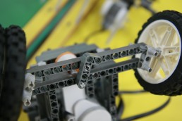 Before: Front wheels without gears |  After: Front wheels with gears |
Our third robot design on 30 July 2011
After we tried out our second design robot with the NXT MINDSTORMS programming, the robot was not able to move over the ridge because the NXT brick is attached on top of the back wheels. So, the robot became unbalanced and it was difficult to move on uneven surface especially over the ridge and MoonBots rocks.
Therefore, we decided to attach the NXT brick right in between the front and back wheels so that the robot is in balance and the gravity is in the centre. At the same time, we also added a third motor to design an extension arm to retrieve Helium-3 elements.
 The NXT brick is in between the front and back wheels | 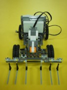 Third motor with an extension arm |
Our second robot design on 23 July 2011
We were inspired by a design called 'NXT Steering Rover' from the website http://nxtprograms.com/steering_rover/index.html
Our robot uses one motor for steering, one for driving forward or backward and another as as the arm of the robot. We used this idea and added NXT brick on top. We also use bigger tyres for added traction so that the robot can go up the crater/ ridge.
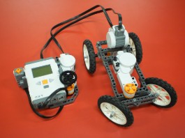 Inspired by the idea of 'NXT Steering Rover' | 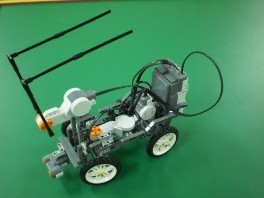 NXT brick and third motor at back of the robot |
Our first robot design on 16 July 2011
The initial design of our robot was to build two big wheels at the back and a big castor wheel in front. Unfortunately, the robot was not able to turn left or right on the LEGO base plates. The robot was able to move forward and backward only.
 The robot is not able to turn left or right | 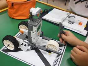 The robot must be able to fit in A4 size |